Sometimes it is necessary to measure additional signals time synchronously with the spectra. In Windows one so called time slice is 1ms. That means you are not able to switch between applications faster than that. Think you have a 2nd PCI board with analog input signals that you want to sample together with the camera signals. Your shot rate is 1ms or even 10µs (@100kHz). You now have the problem that you cannot say exactly what signal belongs to which spectra. One solution would be to save a time stamp together with that data, but you would have to sort out the stamps from the spectra and find the corresponding one of the additional data. That's no easy task.
For that we have the solution that, together with the camera spectra, we can add the additional signals to the data stream. The values are taken directly when the camera read is done. So every data array holds the camera data and the additional signal values as if they were additional pixel values. These values are always synchronized as they are taken and kept in the same data plot.
Our options are:
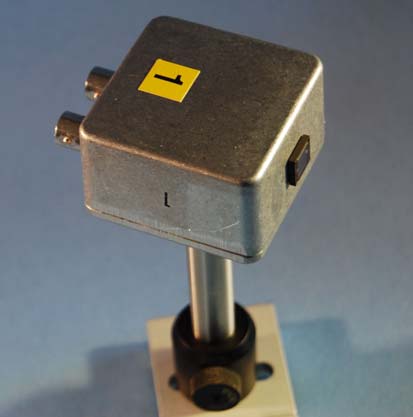
Photodiode Amplifier
Need to reliably measure energy fluctuations of your pump and/or probe pulses with your CamControl system? Our active photodiode amplifier add-on is the answer!
Designed for our CamControl, it takes ultra-fast optical signals and optimally shapes them, by stretching the pulse so our camera control integrator can handle them accurately. It's C-coupled to ignore constant stray light, ensuring you measure the pulse, not the background.
Conveniently powered directly by the CamControl (no batteries needed) and featuring monitor outputs for easy signal checks.
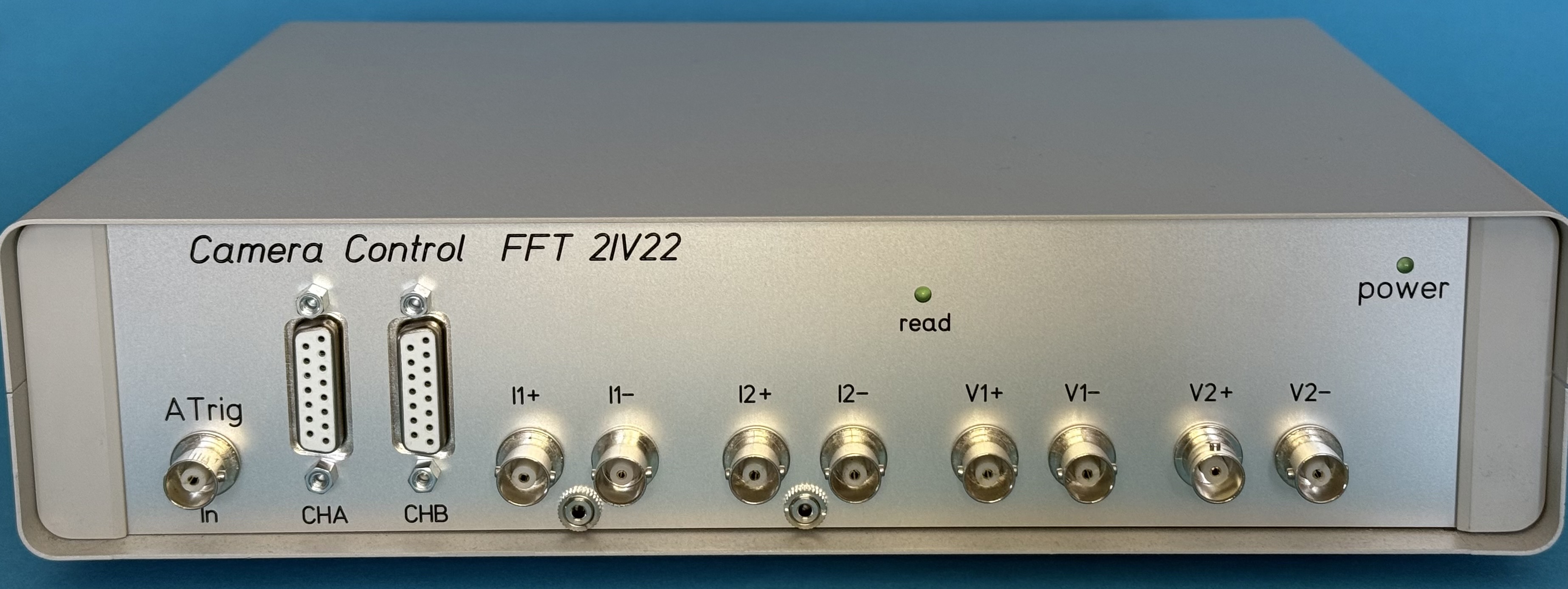
CamControl for 2 or 4 Integrator inputs for additional photodiodes
Can be used to correct pulse energy fluctuations of pump or probe, signal or both.
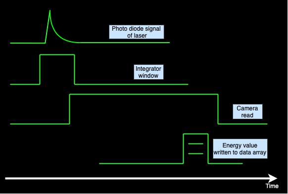
The photodiode signal is stretched by using a slower diode, so the integration is easier to accomplish by the circuit. The integrator timing is controlled by the CamControl (which is synchronized to the camera read) and the energy value is saved to a pixel value of the data array. This works like a built-in boxcar integrator where all trigger signals are implemented already.
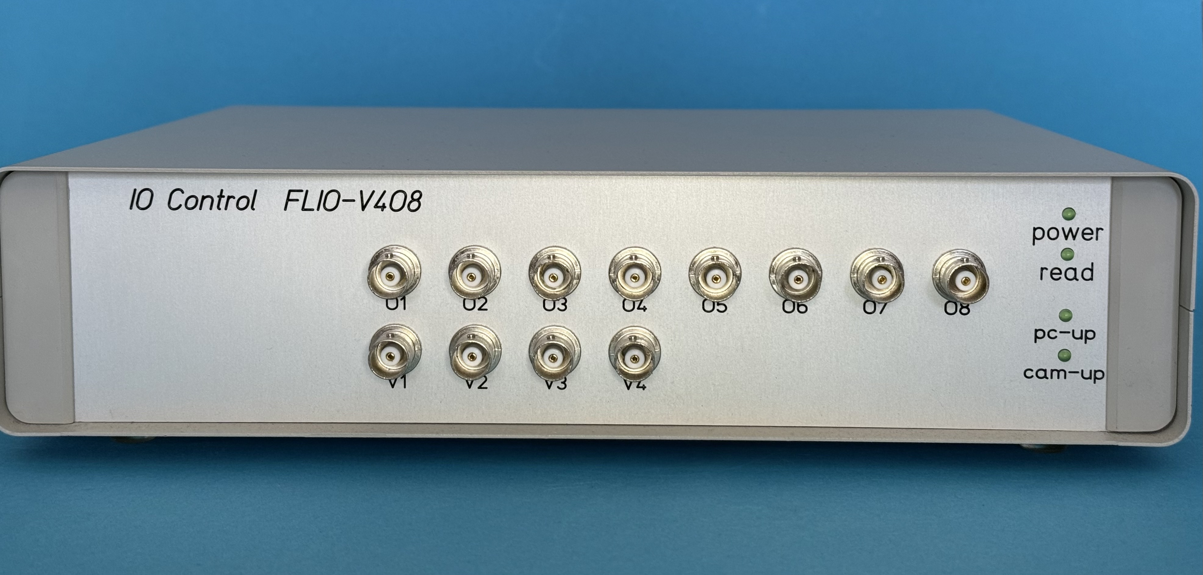
CamControl
CamControl with 2 or 4 Voltage Inputs
This device has a voltage DC input of 0-10V (or 0-5V), which can be used to store delay stage positions or other DC signals (i.e. Boxcar) in every scan. The signal is taken when the camera read is done and stored in one extra pixel.
CamControl
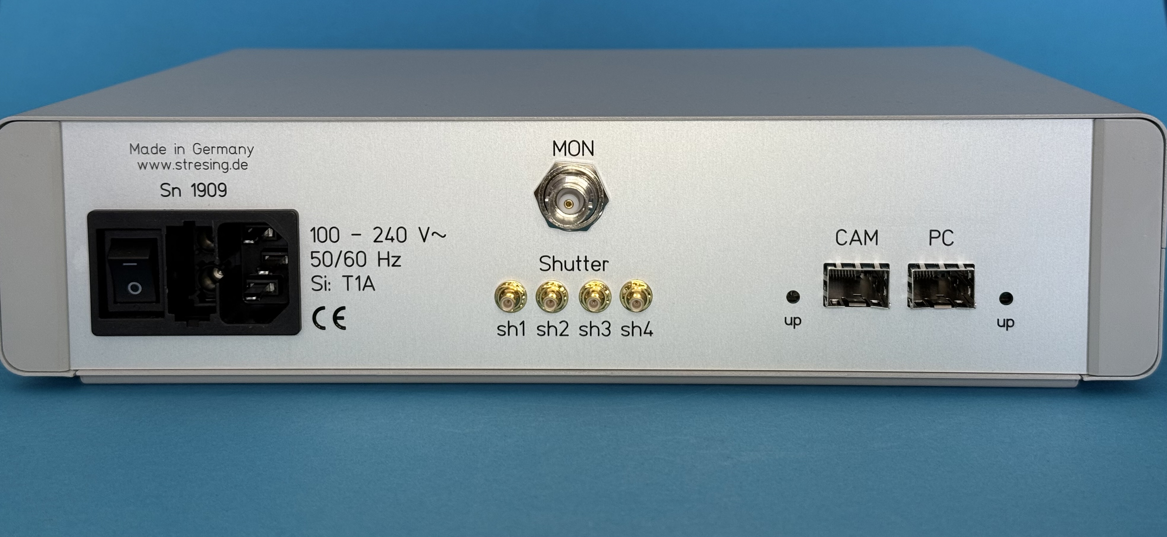
Shutter Control Connector
For the measure sequence, often some simple shutters are needed (i.e. block the light signal for a dark reference subtraction). As you already have our PCIE interface with the fiber cable connection and you have installed our camera driver, you already have all you need to control some additional signal path blocking. All you need is our Shutter. Can be connected to up to 4 connectors (sh1 to sh4) which are implemented in our CamControl.
Mechanical Shutter
Closing time: 30ms
Blade thickness: 0.15mm
Material: aluminium alloy
Surface: matte black
Delay Stage Position Counter
Here the direct sync motor signals of an optical delay line are counted (32 bit) to store the
stage position of 2 mirrors.
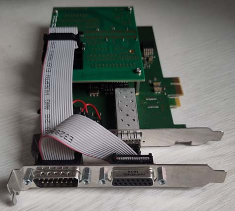
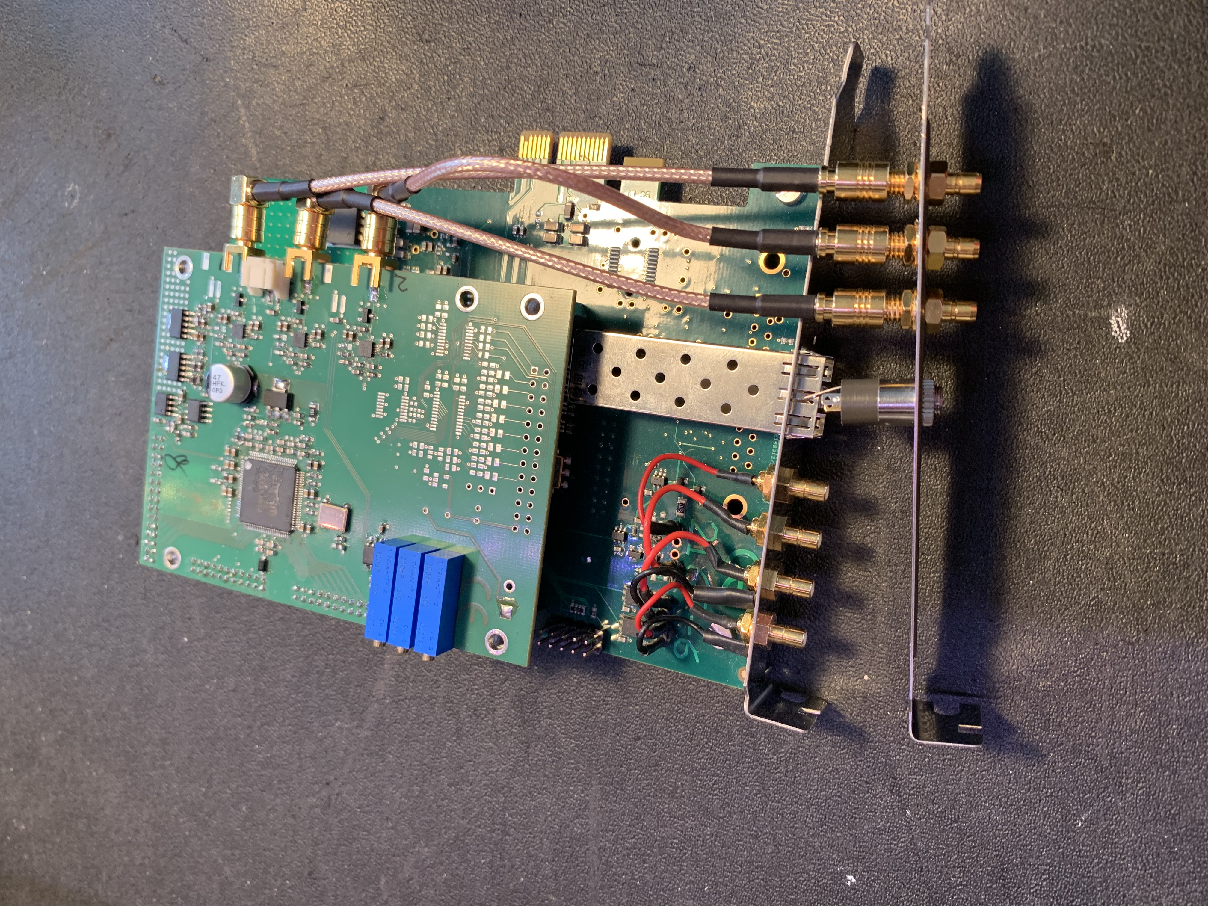
The delay position is transfered with 2 phase shifted digital signals, which can be counted
by our daughter board. This board is mounted on our PCIE interface and can store the
positon value with every read.
So in every scan, the correct position of the mirrors is
stored
in
one pixel.
We have implemented 2 channels for 2 delay motors.
This option is also known as rapid scanning, as this speeds up the standard procedure of 1) move to position, 2) take thousands of scans, 3) move to the next position. You can now let it go during the scanning.
Time Delay Counter
The signal delay of 2 fast photodiodes can be
This is a daughter board for our PCIE interface.
Specs:
Range: 30ps - 40µs
rms-jitter: 2 counts,
ptp: 8 counts
1 count = 27ps (32-bit register)
8-Channel Delay Pulse Generator
This option is a complete pulse generator with 8 channels. Here you can program a sequence of 8 TTL signals (0/5V) where the delay and duration of each channel can be set individually with 100ns resolution.
This can be used as a pulse generator for the whole timing sequence control.